One of my friends recently got a new radio (an Icom-706MK2G), and wanted to try the 15m band. We did not yet have an antenna for 15m, so it was a perfect excuse build another ground plane antenna (more details about the construction can be found here: https://m7isy.rootfs.net/2025/02/28/building-a-1-4-wave-ground-plane-for-20m/). It was the third time building this type of antenna, and other than needing to cut the wires to a slightly different length, the procedure was the same as the previous two times.
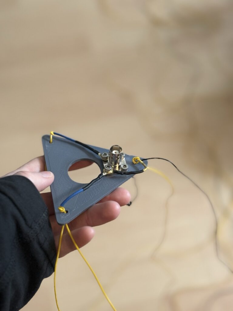
As can be seen from the above picture, this time, we had a different shape of BNC connector. The new connector is the one on the left, and the surface area of the ground is much larger compared to the previous BNC connector we used. This meant that it was much harder to heat up, which made soldering the wires to it much more difficult. However, we managed to get everything attached, covered the connections with heat shrink, and fixed the wired in place with some tape. Finally, we assembled the antenna, double checked the SWR with the nanoVNA and were ready to transmit! As the sun set, it got too cold to sit outside. Therefore we decided to relocate the antenna, so that we could sit inside, and route the coax through the window.
We double checked that the SWR looked good on the nanoVNA, and then connected everything up to the radio – where we were greeted by an SWR of infinity! What? How was that possible? Perhaps the PLC-to-BNC connector was the problem? We swapped the connector to another one but still the SWR showed infinity. Confused, we connected my Yaesu ft-818nd, set the power low, and saw that it gave us a good SWR measurement. Could it be a problem with the ICOM-706 itself? Time for the 50 Ohm dummy load!
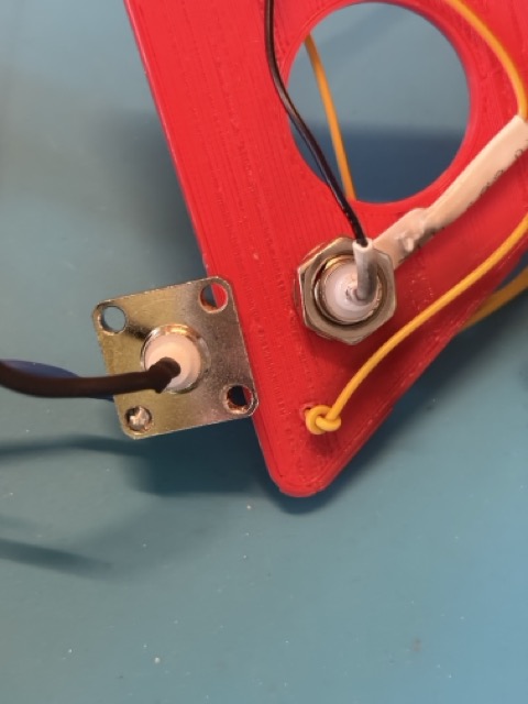
First, we attached the dummy load directly to the antenna output on the Icom-706MK2G, and to our relief, we saw that it measured no SWR – exactly as expected. Phew, that meant that the problem was unlikely to be the radio. Then we put the dummy load on the other end of the coax. Again, we got the expected measurements. That meant that it must be the antenna? We had fixed the wires to the 3D printed base plate with blue tape, meaning that the connections were covered up. Peeling off the tape revealed that two out of the three ground plane wires had come loose! It must have happened during the relocation of the antenna.
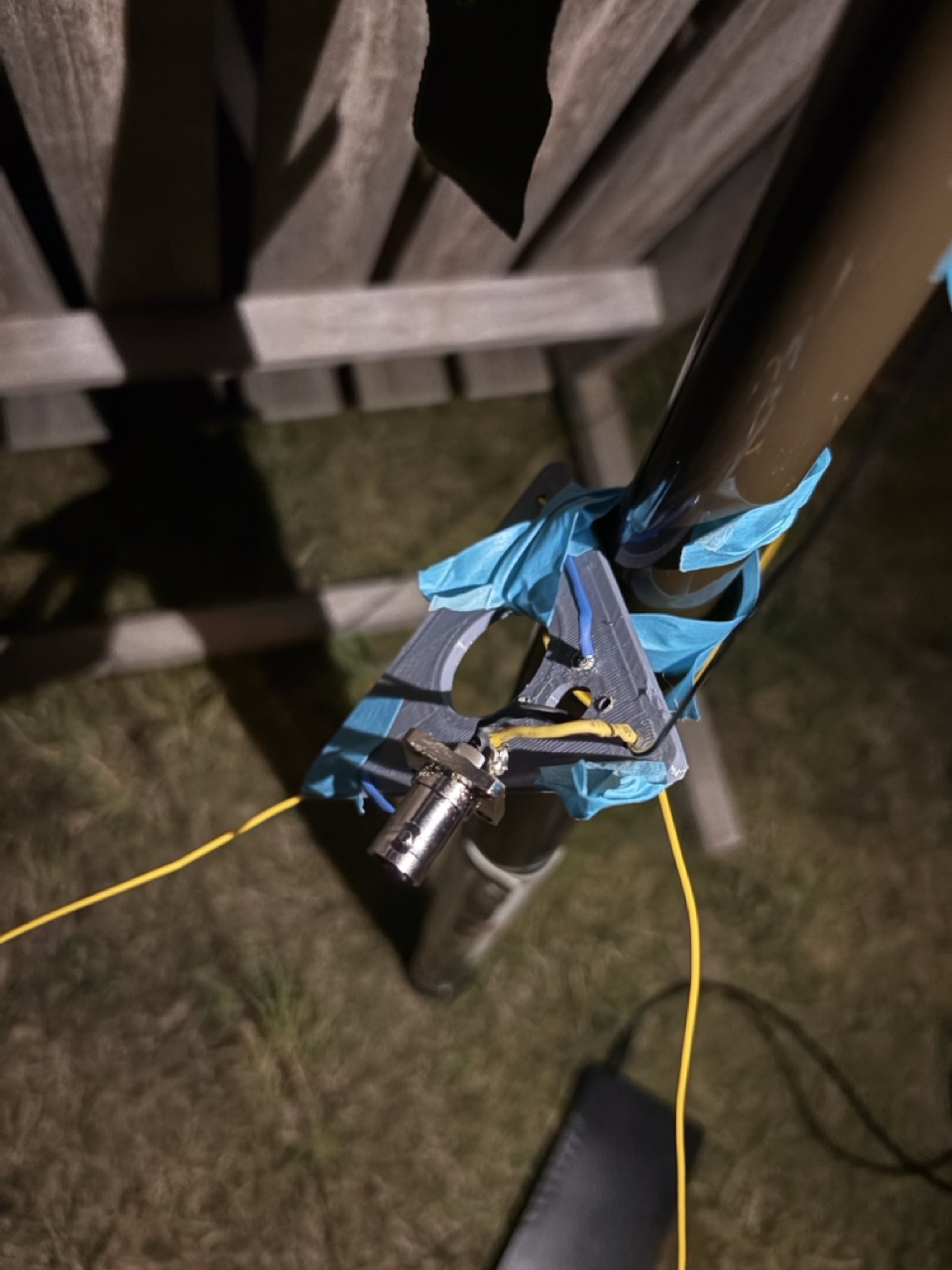
The above picture shows the loose connections on the base plate (which is taped to the mast with sticky tape as the hole for the mast was too tight, so we improvised). Although we attempted to solder the wires again outside, the base plate was too cold and wicked away any heat that we were putting in, so we needed to repair it at home. Instead of attempting to solder the wires this time, we attached them in place with screw terminals, and knotted the wires above the holes to reduce the pull on the actual connections.