
Being limited to the 10-Meter band for HF in germany, and the 10-Meter band being susceptible to rapid band condition changes, the ability to make contacts greatly depends on the propagation for your current location.
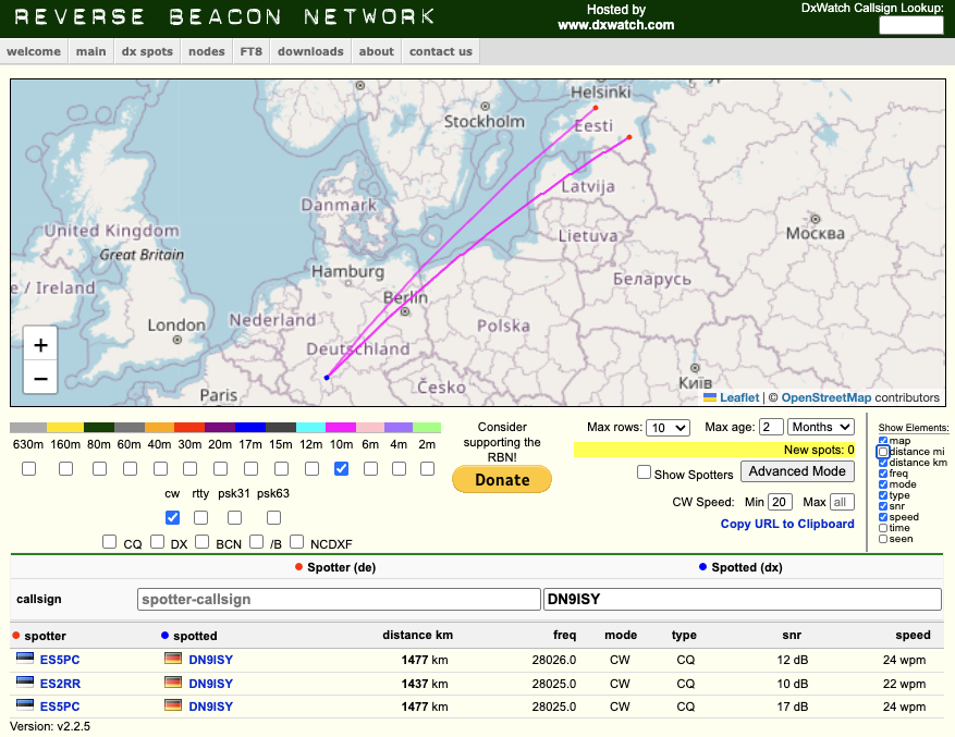
To get an idea of where in the world I can be heard under the current conditions, I do a short transmission to the Reverse Beacon Network (RBN). Afterwards I can open their map on my phone to check, which stations on the world detected my transmissions. As I mostly operate portable, I constantly have to re-set-up my antenna and usually transmit from different locations each time.
The reverse beacon network consists of stations all over the world that are listening on all sorts of bands for CW. Whenever they manage to receive and decode a callsign, they will report their location, the received call sign and signal strength to the website, where it then is displayed on a map. To be picked up by the RBN, you simply need to transmit something in CW like:
TEST DE M7ISY M7ISY M7ISY TEST DE M7ISY M7ISY M7ISY
If you aren’t fluent in CW (yet), but have a modern radio, you usually can pre-type a text that the radio will transmit in CW with just a single button press. That’s how we do it with G8DUK and his ICOM-705.
But my YAESU ft-818nd is too old to support that feature, so another solution is needed. Initially I tried connecting a paddle and give the CW manually. That did not work very well, as my keying was too notchy for a computer to decode it. I was talking to my friends about that issue and one of them came up with a promising idea: Let’s build an external device that will connect and behave exactly like a paddle, but fully automated.
The concept and basic testing
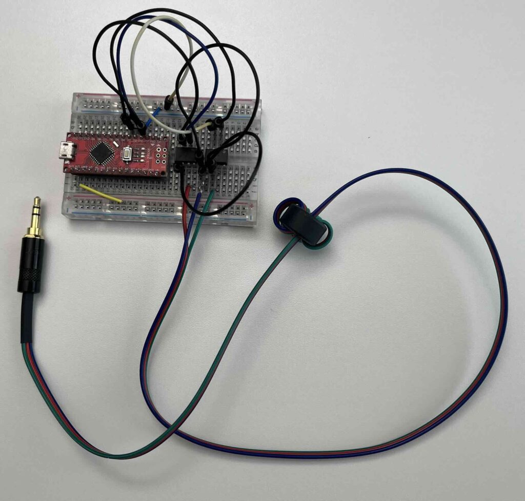
We started simple on a breadboard to allow for rapid prototyping. The initial idea was to use an ATtiny microcontroller as brain of the device. While researching prices, we were surprised that buying an ATtiny is pretty much as expensive as buying an Arduino Nano, which uses a more powerful microcontroller (ATmega16).
A “real” (paddle-) keyer is connected to the radio with a three-stranded-wire. One strand can be labelled “common”, and then there is one strand for “DOT” and one for “DASH”. When you press a paddle on A Key, it shorts either the “DOT”- or the “DASH”-Wire to “common” (Exactly like a switch works). This is something we have to Imitate with our project. The first idea was to use transistors as switches and operate them through the microcontroller. We decided against that, as we wanted to keep the radio and the microcontroller circuits electrically separated. Our thought process was: Whatever faults might happen with the microcontroller circuit, it should never be a risk to the expensive radio it is connected to. (Maybe we are a bit overly cautious here, but: Better safe than sorry). Our thoughts then went towards relay switches. These allow to the switched by a microcontroller and provide a galvanic insulation between our circuit and the radio. But in the end we went with optocouplers. While a relay switches on and off mechanically, an optocoupler has no moving parts. They make use of an LDR, or Light Dependent Resistor, a type of resistor whose resistance decreases as the light intensity shined on it increases.
This is the first iteration, still on a breadboard:
The next step: Designing a PCB
After using this very fragile solution for a while, we decided to transfer this circuit onto a printed circuit board (PCB). We started by drawing a schematic in KiCAD, a free and open source tool to design PCBs:
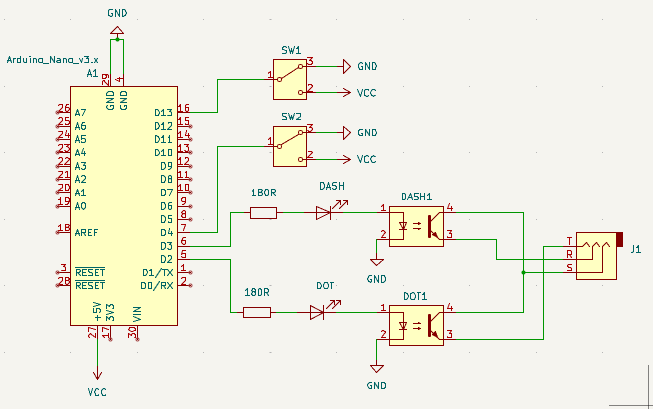
You might notice, that the two switches from the schematic are missing in the actual prototype. The position of those switches can be read by the microcontroller. They can be used as “input” devices to change the behaviour in the field. The idea of adding those came to us last minute, directly before getting the PCBs manufactured. One switch shall define, which of two stored call signs should be transmitted. The other one is intended to switch between two CW speeds. But as the actual logic behind that is implemented in the software on the microcontroller, those switch functions can be changed dynamically. Doing this changes last minute and not testing them on a breadboard before was a stupid idea. You will soon see why….
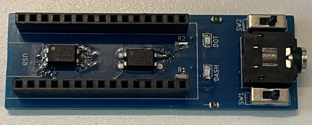
After waiting for 2-3 weeks, the manufactured PCB arrived in the post:
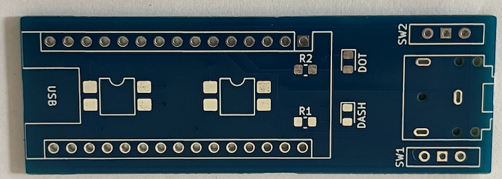
Price-wise it was not a big investment. We ordered 15 pieces and paid $3.10 for all of them, including shipping to Germany. For some reason, we received 20 pieces, instead of the 15 we ordered. We don’t know if this happened by accident or if due to the way those are manufactured, they had to make a batch of 20 anyways.
While waiting for the PCBs we ordered 0805 SMD resistors and LEDs in multiple colours. The SMD-Optocouplers we already had. For a spool of 300 SMD resistors we paid 1,40€. For the LEDs we managed to get a kit of 6 colours, with 100 LEDs per colour for 2,59€. That should be enough LEDs for many future projects to come. Delivery took around 2 weeks and was faster than the PCBs. Once arrived, we soldered the components on one of the PCBs for a first test and immediately spotted three major issues:
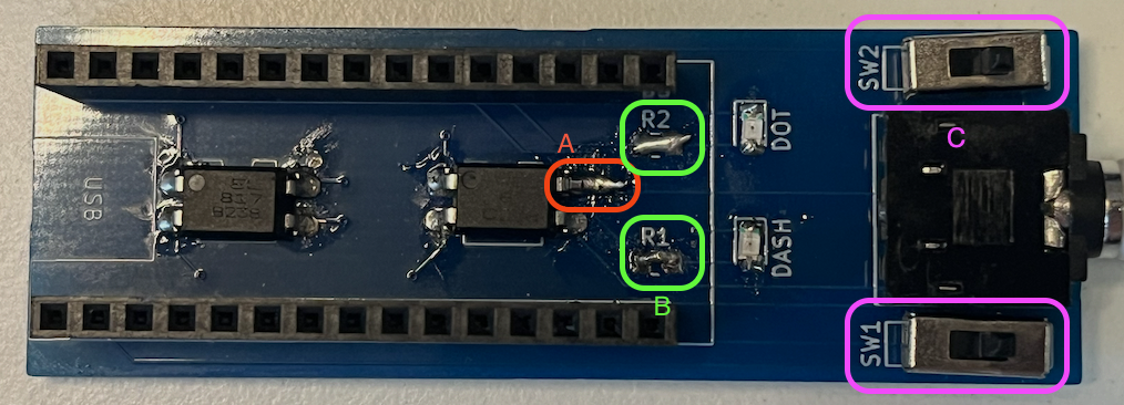
- A: That pad of the optocoupler is not connected to any trace on the PCB. The trace it is supposed to connect is very close by, but moves to the backside of the PCB through a “via” just a few millimeters away. We managed to patch that, by carefully grinding of the coating on top of the via, to expose the bare copper trace. Then an extra long solder-joint connects the pad with the trace.
- B: Putting the optocouplers in series with the LED and resistor caused either the voltage to drop too far or the current to be too limited to operate the optocouplers. The power available to the couplers was just not high enough to trigger the output side. When using yellow and orange LEDs, it was enough to de-solder the resistors and bridge the two pads together. For that we used the cut-off legs of the switches we soldered in earlier.
- C: Apparently the microcontroller is not happy about having it’s analog input pins connected directly to VCC without any current limitation. While it was perfectly able to detect the position of both switches and adjust the executed program based on it, the microcontroller got quite hot, whenever the switches were in the HIGH state. A solution would be to put a 1k-ohm resistor in series, between the microcontroller and the switch. After taking the above picture, that is what we ended up doing. We carefully cut the traces going from the switches center pin towards the microcontroller. We then ground the PCB coating next to the cut, in order to expose the copper trace and solder an SMB resistor directly to it. (As we only had our 180 ohm resistors at hand, we used those. – And it worked fine)
All of the above issued could have been prevented, if we would have invested just a bit more time upfront to test the circuit on a breadboard, and double-checking the traces before ordering the PCB. Please don’t judge too hard on how the solder looks on that PCB. This is the result of soldering, de-soldering and then re-soldering all components multiple times, in order to find the mistakes.
Bridging the resistors helped only for yellow and orange LEDs. It did not work, once we used green and blue LEDs. Our assumption is, that the voltage drop across them is too high to power the optocoupler in series. We revised the circuit diagram now to have the optocoupler and the LED wired in parallel, to avoid this issue in the future.
But: It’s not our intend to throw away 20 PCBs that (except of those patchable issues) work fine. Assembly will now be much harder and time consuming than expected, but it would feel like a waste to just replace those PCBs with a new batch.
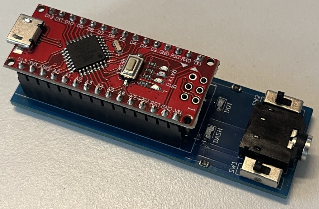
This is the PCB with the traces for the switches cut and resistors soldered in. With an Arduino Nano attached, the complete keyer:
The software
What we built with the PCB is just a way to send the CW-Keystrokes to the radio without any electrical connections between the radio and our circuits. We still need something to generate those keystrokes based on some predefined text.
The pin headers on the PCB allow to simply plug in an Arduino nano board (or cheap knockoff), that can be obtained for around 2€. We decided against directly soldering to the microcontroller, so that it can be easily removed and reused for later projects.
To write the software for the microcontroller we use a free tool called “PlatformIO”. It can either be installed as dedicated application, or as a plugin for “Visual Studio Code”, a free and powerful code editor. As we already had Visual Studio Code installed for other projects, we decided to use PlatformIO as a plugin. In VSCode press Ctrl + Shift + X to open the extension list. Search for “PlatformIO IDE” to install PlatformIO.
The source code (and also the KiCAD files for the PCB can be found on GitHub: https://github.com/hujiko/rbn-cw-keyer
Download the repository to your local machine and open VSCode. In the left side, there should be an icon looking like an alien-head. Click that to open the PlatformIO quick access menu. In there, click “Open”, and in the then opened PlatformIO interface “Open Project”. Navigate to the downloaded files and select the “microcontroller-software” subdirectory.
In the small bottom bar of PlatformIO you should now see a row of icons: A house, a checkmark, an arrow pointing right, a trash can, …
Click the “Checkmark” icon. This will start compiling the source code. it should open a small terminal within PlatformIO and after 1-2 seconds, a green SUCCESS should indicate a successful compilation. Now connect your Arduino with a USB-Cable to your computer and in PlatformIO click the icon of an arrow pointing right. This should upload the project to your microcontroller. When doing that, you can either remove the microcontroller from the PCB, or leave it in. Both works completely fine.
Expect to see a green “SUCCESS” at least for “nanoatmega168”. Don’t worry if you see an error for “attiny85”. As stated in the very beginning: We decided against using this microcontroller, as the financial benefit was not worth the limitations it brings.
Unless already done, insert the Arduino into the pin headers of our PCB now. You can power the keyer with a USB-Powerbank and connect it to your radio via an audio cable. One end of the cable needs to be a 3.5mm stereo audio jack for the Keyer. The other end depends on our radio. (Usually either 3.5mm or 6.35mm stereo audio jacks).
Tip: The keyer draws very little current. Some powerbanks turn off after a while when they don’t detect a big enough load. If this happens to you, either remember to press the “on” button every few seconds to prevent the power bank from turning off, or if your power bank has more than one socket, connect your phone or any other load in parallel to prevent it from shutting off.
A quick try with a self-built ground-plane antenna for the 10 Meter band and 6 Watts on a YAESU ft-818nd (during horrible band conditions) caused us to be spotted in Estonia. Seems like despite the issues with the PCB, the project was a success!
We still have some PCBs that I am willing to hand out, in case you are interested to build/own a keyer for yourself. Feel free to contact me here or on Instagram. And if you already built one, or use something else to do the same job, I am curious to hear about it too.
UPDATE: I was told, that this does not seem to work on an ICOM-705. This keyer should not be necessary on an ICOM-705 anyways, as that radio comes with a built-in text-to-morse function. But I am anyways curious why not. So if I manage to get my hands on an ICOM-705, I want to debug to get to the root cause.